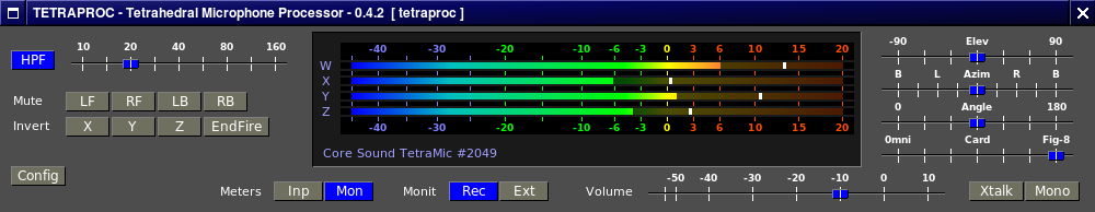
TetraProc's main window. This contains all the controls you need during recording.
- Left: recording controls - high-pass filter, A-format mute and B-format invert swiches.
- Center and bottom: metering and monitoring.
- Right: virtual microphone for stereo monitoring or recording.
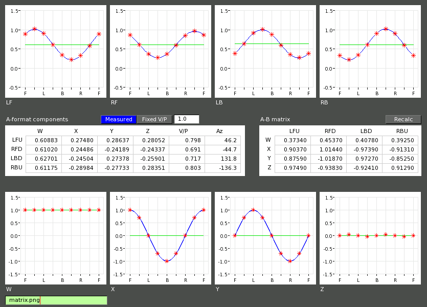
TetraCal's matrix calculation window, showing results for a Core Sound TetraMic
The red dots in the the four plots at the top show the polar responses
of the four A-format mics, derived from impulse response measurements in the
horizontal plane. The blue, sine-shaped line is the first order response best
fitting these points, and the green line is the zero-order component.
The four
mics are very well matched, but there remain small differences in sensitivity
and directivity. These are unavoidable even when using the best capsules, and
are the reason why each tetrahedral mic must be individually calibrated.
The left matrix is a numerical representation of the same data. The one on the right is the computed A-B matrix that will be used by TetraProc, and that will produce the correct B-format polar responses for this microphone.
These are shown in the plots at the bottom. W,X,Y are a perfect omni and two bidirectionals respectively. A small second-order residual is visible on Z, which is otherwise zero since all IRs are taken in the horizontal plane. This residual is normal and exactly fits what is predicted by the theory.
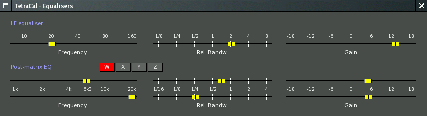
TetraCal's equalisation window.
This is used to adjust the parametric EQ that together with the A-B matrix shown above will turn the A-format signal into Ambisonic B-format. The EQ is adjusted manually while observing the results in the window shown below.
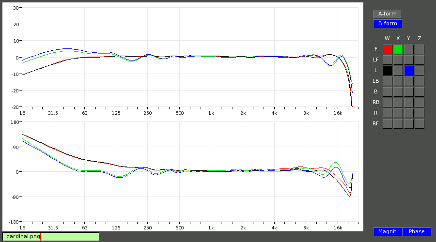
TetraCal's frequency and phase response display, showing W,X,Y response for a front and a left source.
A few things should be noted about these plots.
This is a raw technical measurement result, not one that has been doctored
to look good for a sales brochure. You should know the difference if you have
ever measured a mic yourself.
If correctly interpreted this picture shows how very good the result is, but
some aspects need to be explained.
* The wobbling LF response for X and Y, and the apparent rise at the extreme
LF end are an artefact of the measurement method. The impulse responses used
have been recorded in a room that is not completely anechoic - there are some
reflections, and the LF part of these remain in the IRs even after
frequency-dependent windowing. For the W-response, the reflections can be
removed even at LF by using a reference measurement recorded using an
omnidirectional microphone. This works because W is also omnidirectional.
But the reference channel cannot remove the reflections on the bidirectional
components.
If the measurements were done in a perfect anechoic room then X and Y would
be as flat as W is, and the curves would match except for the proximity
effect on the first order components.
* The dip for X,Y at 12.5 kHz, (and the corresponding phase response) is
typical for any tetrahedral microphone at the two source directions
shown in this figure. It is the result of the finite distance of the four
capsules that make up the microphone. A smaller radius would move it up in
frequency, and a larger one would move it down proportionally.
Best subjective results are achieved by NOT trying to remove this small dip,
as this would have a negative impact on the overall frequency response.
* The LF roll-off at 30 Hz is intentional. It is possible to extend the LF
response, but the result would be a microphone that would be difficult to use
in most practical recording situations - it would be extremey sensitive to air
currents, passing underground trains and distant earthquakes.
Actually, almost no classical (non-tetrahedral) directional mic would
have a LF response and LF polar diagrams as good as this one.
* The small phase diffence at HF between X and Y is just because these are two separate measurements - if the mic is displaced by just a few millimeters while it is being rotated, this is what can be expected.
Taking these points into account, the results are really excellent, and
much better than what could be achieved with analog A-B processors.
Note the perfect matching of the responses for the two directions, for both
the omnidirectional and the first-order components, and also between them.
This is confirmed by looking at the other directions.
Near-perfect omnis may exist (most still have a 'preferred' direction),
but no real figure-of-eight mic will have such accurate polar patterns over
almost the entire frequency range.
This means that after calibration this microphone is not only an excellent
Ambisonic mic, but that it will also be a very good one for stereo recording.